Sliding-Mesh SD/FR Method
Sliding mesh is handy in dealing with rotating geometries. However, it introduces nonconforming interfaces between subdomain meshes. To overcome this geometric incompatibility, we have developed a curved dynamic mortar method. The figure below shows the sliding mesh for a Taylor-Couette flow simulation, as well as the distribution of mortar elements between two subdomains.
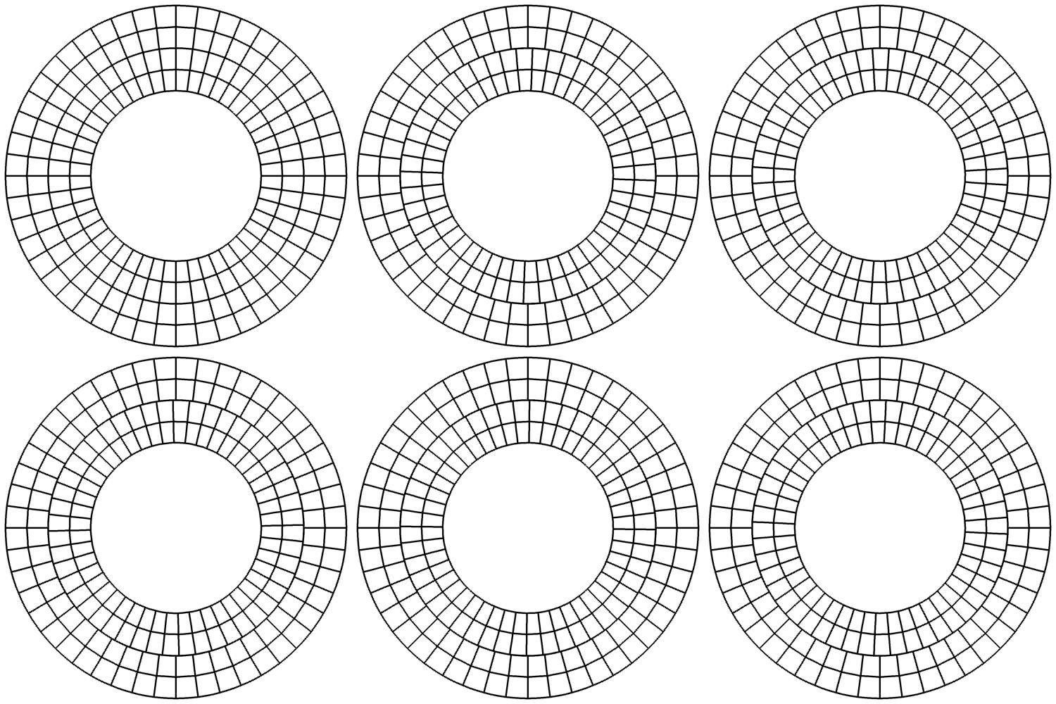
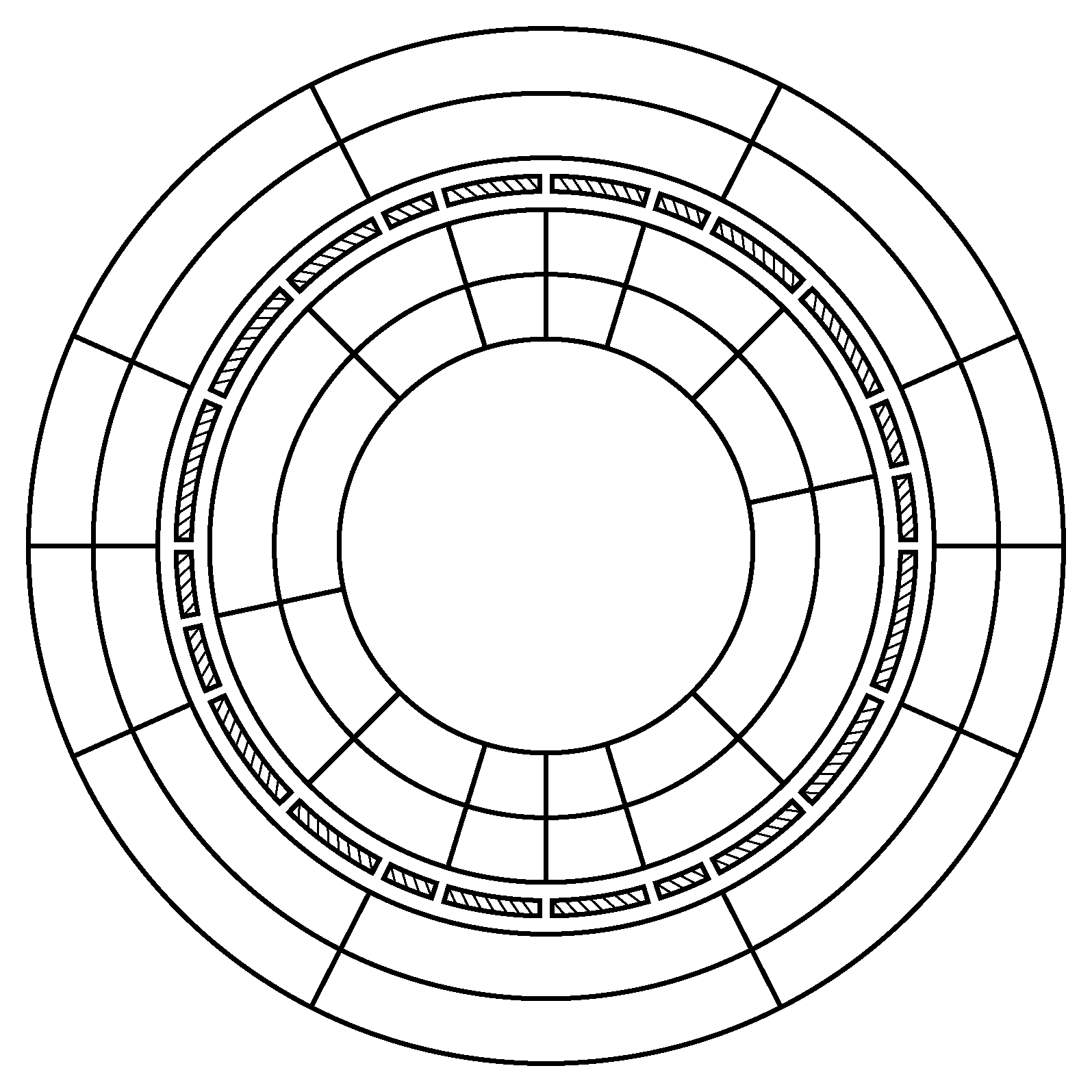
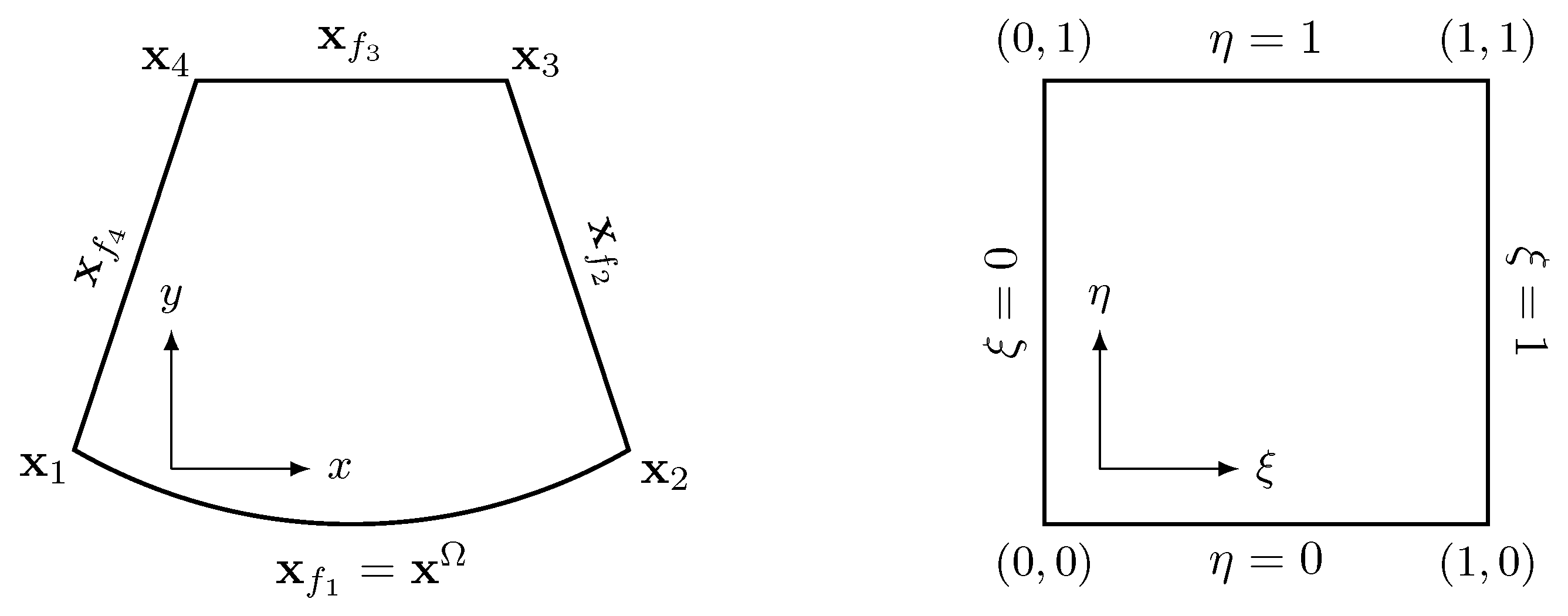 Since the sliding interface here is circular, we employ the following transfinite mapping that introduces no geometric error for elements along a sliding interface,
where is the analytical expression of the -th cell face, and is the coordinate vector of the -th corner node. For example, the circular face has the following analytical expression,
where R and are the radius and the center of the underlying circle; and are the angles of the two nodes. The changes of a sliding cell face and its mortars during this process are illustrated in the figure below, where and denote cell face and mortar, respectively.
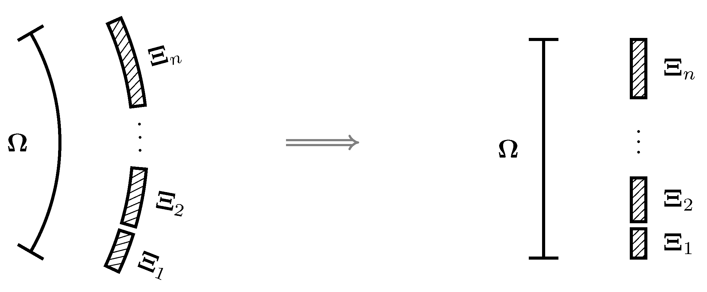 The mortar space and the computational space are related through the following offset and scaling (OS) relation,
where represents the physical length of the corresponding element.
Step 2: project solutions from cell faces to mortars. The figure below demonstrates this process for the left side of a mortar.
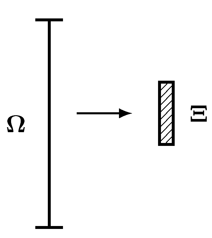 The projection is
The same process is applied to the right side of each mortar.
Step 3: compute the common inviscid flux and common solution on a mortar element using the left and the right solutions.
Step 4: project the common values from mortars back to cell faces as demonstrated in the figure below.
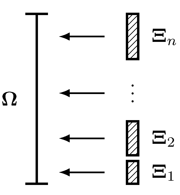 Taking the flux for example, the projection is
where is the number of mortars associated with the cell face, and is the unknown common inviscid flux on the cell face.
Steps 2–4 are repeated for viscous fluxes if it is a viscous flow. It is worth mentioning that mortar and cell face connectivities as well as the OS relation need to be updated at each stage of a time marching scheme.